COBRA Frequently Asked Questions:
- Can I get the user manual and the SDK programming manual of COBRA?
- I have downloaded the latest COBRA package, but failed to install it. What do I do?
- When I start COBRA, I get the splash screen with the logo, but then nothing happens. What is the problem?
- What formats are accepted for the input projections?
- Can slices be saved with .dcm file extension? Is it possible to modify the tag values or add new tags into the DICOM header?
- What is the difference between the tags PARTAG_PROJACQUIRED and PARTAG_PROJRECON?
- How are tags PARTAG_DETOFFSETU and PARTAG_DETOFFSETV defined?
- How to calibrate the reconstruction output to Hounsfield Units?
- Can you give more detail on PARTAG_MINUS1000, PARTAG_SCALEFACTOR and OPTAG_SLICESCALE?
- Can you please give us more detail conceptually about how extended view reconstruction works?
- Is it always better to run a detector at its full resolution?
- What are OPTTAG_ZFILTERN (N = [0-15]) used for?
- What is the use of PARTAG_INPUTDOWNSAMPLE_X and PARTAG_INPUTDOWNSAMPLE_Y?
- What is protrusion correction and which parameter do I need to set?
- In the later versions of COBRA, SAMARA Parameter Adjustment tool is missing. How do I obtain the values for SAMARA parameters?
- Is it possible to generate .bin files for the geometrical parameters depending on the angles?
- What are these text files found in COBRA work directory: ANGLE_ARRAY, HORTILTING_ARRAY, ORIGDETDIST_ARRAY, etc.?
- Why every time the reconstruction is executed, COBRA modifies the file "parameter.xxm" defined by the user?
- Is it possible to insert in the file "parameter.xxm" the value of detector pivoting?
- Is the geometrical calibration in the extended view mode done differently from a normal calibration?
- Could you please help us by telling us the operations that you do to create and apply the projection matrices?
- How to install (uninstall) COBRA manually?
- Is Cobra working (compatible) with Windows XP 64 bit and Vista? Does Exxim have any plans to offer a special 64-bit version of Cobra?
- Give some more information about the data types and sizes of the preprocd_proj.000 file?
- How to define a factual slice number that have been saved on the disk in a stacked volume mode.
- Which type of PC (hyperthreaded, multi-core, etc.) should I use to get the best performance?
- How can I make a calibration phantom myself?
If you do not find your question being answered here, please contact us.
|
1. Can I get the user manual and the SDK programming manual of
COBRA?
They are
included in the COBRA installation package. They can also be directly
downloaded from our website at 2. I have downloaded the latest COBRA package, but failed to install it. What do I do? The detailed installation instructions are given in the User Manual included in the installation package, or you can view it from here. Generally,
Every time you re-install COBRA please make sure that you completely uninstall it. You may need to make a global search for the following files and make sure that they are deleted:
If by some reason the installation does not finish, please consider a manual registering of COBRA components (see #22 below):
Cobra has a rather complex architecture (because it may be "spread" over a network) so its installation and functioning might be "confused" by many factors. First, please disable your antivirus (AV) software, if you have it permanently running and scanning. Cobra is based on Windows Service concept which may malfunction due to some AV packages (COBRA's ability to start and control processes on remote PCs looks highly suspicious to AV). Conventional Windows Firewall usually does not introduce problems, but in the initial installation please also turn it off. Should there be any additional questions regarding this matter, please email us. Secondly, if the above does not help, please uninstall Cobra, and make sure that there are not any "leftovers" (you may need to make a global search for guard.exe, BackPrj_COM_Server.exe and BackPrj_COM_TCP_Service.exe). Then install it again. It is also important to make sure that there are not any “conflicting” programs and services installed. The particular package we know and which may cause conflicts is MAC mobile device support. Please consider not using / un-installing this or migrate to Cobra with version mark starting 6.4.7. Cobra version 6.4.7 gets the additional program called checkPorts.exe (see # 22 below). Obviously we are testing our setup package on some variety of PCs (different vendors/platforms) but our set is not comprehensive. So we can not exclude the situation when the configuration you have is potentially causing the problem. If this is the case, we may set up a GoToMeeting web conference where we will be able to gain temporary control over your PC, and figure out what is wrong with your installation.
4. What formats are accepted for the input projections?
COBRA provides output into a subset of standard DICOM format; restrictions are: 1) One file per image (slice) As you see since our format is rather simple and straightforward and we did not create situations that any viewer/workstation could not handle. At the same time, obviously, we cannot exclude a situation when a tool you have by some reason and in some point "is unhappy" with our DICOM. In this case, we will need more information form you. Some further comments: 1) DICOM file names do not necessarily possess .dcm extension. Getting .slice extension does not mean that they are not DICOM files. If you prefer .dcm please set it up through OPTTAG_SLCNAMEFORMAT. For example
2) Created files contain DICOM header with a minimal set of DICOM tags. The demographic tags are generated using "dummy" values (see below); the geometry is available and grabbed from .xxm files. After first reconstruction you can observe these parameters in the research.xxm file in the source data folder. This file contains all tags applied. The syntax is very simple. For example, for study description it will be
This file can be pre-created or/and edited. For example, you may add new tags you need:
Also see User Manual Section 5.2
6. What is the difference between the tags PARTAG_PROJACQUIRED and PARTAG_PROJRECON? Here is (unfortunately) some mixture of historical and ambiguous issues.
7. How are tags PARTAG_DETOFFSETU and PARTAG_DETOFFSETV defined? They represent the central ray position and are defined in the detector coordinate system. Set the origin at the center of the detector (Nx/2, Ny/2), the intersecting point of the central ray with the detector surface has coordinates (PARTAG_DETOFFSETU, PARTAG_DETOFFSETV), measured in pixels. The central ray is the ray through the center of rotation within the equatorial plane (assuming that the tube trajectory is confined in a plane). Positive sign means the central ray hits the detector to the right and below the physical center.
8. How to calibrate the reconstruction output to Hounsfield Units? Regarding parameters that have to be used for calibrating a scanner: a) PARTAG_SCALEFACTOR in general does not make any impact; it is canceled out. COBRA pipeline is the following: How to calibrate: We would recommend doing it with a water phantom fitting into the field of view. Check the output water density and correct OPTTAG_SLICESCALE accordingly. For example, if the output water level is 500 and the applied OPTTAG_SLICESCALE = 1.25, it then is necessary to set OPTTAG_SLICESCALE = 2.5 to get the density of water as 1000 (mg/cm3).
9. Can you give more detail on PARTAG_MINUS1000, PARTAG_SCALEFACTOR and OPTAG_SLICESCALE? Regarding PARTAG_SCALEFACTOR / OPTTAG_SLICESCALE and where it comes from: Lets assume that we are dealing with raw data. We typically get 15 bit ADC values as input signal, giving a dynamic range [0,32767] The scale factor 1000 is the default for biological objects and this is what you get if you put -1. Please keep in mind that (as stated in the User Manual, part 6) the auto-detection procedure may fail (it always could) and it is better to set up this factor from analyzing file preprocd_proj.000. The picture is a little bit different if you have high contrast objects like metal in the projection. The filtered image gets bigger dynamic range (higher gradients), so one should apply a reduced scale factor. For the dental cases, we always recommended 300-500 instead of 1000 (100 is probably is too low). Regarding the difference between 100 and 1000: With a scale factor of 100, for "biological regions" of your projections you get the dynamic range [-2400, +2400] (approx), instead of 24000, which is totally fine. And please keep in mind that PARTAG_SCALEFACTOR is "compensated out" before slice dumping. The slices with 100 or 1000 as PARTAG_SCALEFACTOR will have the same density numbers (up to level of digital noise) as long as OPTTAG_SLICESCALE is kept the same. Output signal is the result of the following operation:
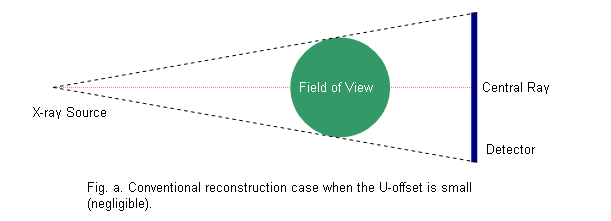
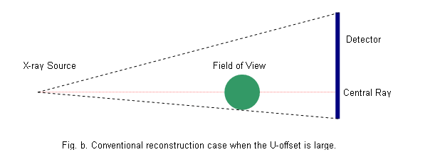
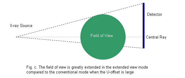
10. Can you please give us more detail conceptually about how extended view reconstruction works?
11. Is it always better to run a detector at its full resolution? Image quality depends not only on detector resolution, but also on the reconstruction voxel size. They have to match to produce optimal reconstructed images. A typical implementation of Feldkamp reconstruction is the so called voxel driven algorithm. Its particular drawback is that each voxel is considered as a point in 3d space. During backprojection, a voxel is being projected onto a projection as a point and receives its value from that spot on the projection, not from an area. To illustrate its effect, let us say your reconstruction cube is 512^3 and your projection is 2048^2. Then the voxels on every vertical slice get contributions only (at most) from 512^2 * 4 = 1024^2 pixels on the projection (a factor of 4 comes from bi-linear interpolation). The rest of the detector pixels (2048^2 - 1024^2) will not be taken into account. Therefore making much finer resolution for projections is going to make the reconstruction result noisier. In other words, beyond the balance point Cube resolution ~= Projection resolution / 2, you do not gain anything in final images but noise. This particularly means that to get a 512 cube, it is better to downsample the projection size from 2048 to 1024.
12. Is it always better to run a detector at its full resolution? Similar to the horizontal convolution, COBRA provides an option to do vertical convolution or smooth, with a maximum window length of 31 pixels. The tags OPTTAG_ZFILTER0 OPTTAG_ZFILTER15 give the convolution coefficients, with OPTTAG_ZFILTER0 at the window center, as illustrated in the following example. The values of OPTTAG_ZFILTERN have to be integers, which will then be normalized internally by COBRA.
13. What is the use of PARTAG_INPUTDOWNSAMPLE_X and PARTAG_INPUTDOWNSAMPLE_Y? To set the downsampling rate for the input projection in x- and y- direction, respectively. Downsampling is done before backprojection thus can speed up reconstruction. It is recommended to use for matching the input projection resolution to the final voxel resolution. A value of 1 means no downsampling is performed.
14. What is protrusion correction and which parameter do I need to set? When an object does not fit in the field of view, the object is said protrude out, and certain correction is needed in order to do correct reconstruction. The tag controls protrusion correction is OPTTAG_PROTRUSIONCMODE. Please refer to User Manual Section 6.7 for its applicable values.
Regarding missing GUI dialog box for SAMARA preview. There are two reasons why we removed the preview box:
We understand that now it may take a little bit more time to find the best fit for SAMARA parameters through regular reconstructions. However it is a more robust way to do it. Also when it's done for a particular scanner/mode it not likely requires re-tuning. Please keep in mind that SAMARATAG_HIDENSLEVEL should reflect a real level of hi-density objects; typically this is the metal. For example for dental cases it is 4000 mg/cm3 (or 3000 HU). So it does not have to be tuned. You also may (and should) try SAMARATAG_HIGHCONTRASTLEVEL and SAMARATAG_LOWCONTRASTLEVEL set to 0. This mode works faster, and does the main job for metal artifact reduction; it is also more robust.
16. Is it possible to generate .bin files for the geometrical parameters depending on the angles? The format of the files is simple: all .bin files contain just a dump of corresponding 4-byte float arrays (no header), one float per projection. Each number, e.g. in uoffset.bin, represents the corresponding u-offset. The u-offset is the distance in pixels between the physical center of the detector and the spot where the central ray hits the detector (also see above). So if one has the means to generate those files it is obviously easy to meet the format requirements. The other side of the story is how to build the corresponding calibration technology. We have to admit that our per-projection calibration tool sometimes fails (the generic task is very hard). For stable geometry scanners, we recommend using another tool (i.e., COBRAGeoCalibration) that is also a part of the package. It provides parameters that are uniform for the entire scan (so basically the output is one .xxm file).
These text files, residing in the COBRA work directory, contain the effective (applied) parameters presented on per-projection basis. If the dataset has (for example) a uniform U-offset, then UOFFSETS_ARRAY contains a set of same numbers.
COBRA modifies the file parameter.xxm in its working directory (default the same folder where COBRA is installed). As long as you keep your parameter.xxm in another place it stays the same. We recommend keeping the xxm files along with the data. The "parameter.xxm" file located in the work directory should not be used as a regular parameter file.
19. Is it possible to insert in the file "parameter.xxm" the value of detector pivoting? The pivot now can only be supplied via pivoting.bin file. A new tag will be introduced to specify static detector pivoting in the .xxm file in next COBRA release.
The calibration in extended view is different from normal calibration, but they both can be done by COBRAGeoCalibration or COBRA_Geo. Please refer to the User Manual for more detail.
From our experience such matrices are used when tube/detector trajectories are substantially complex and can not be described by set of parameters that are uniform for the entire scan. So every tube/detector position has to get some individual description. If the detector is isotropic and orthogonal (this is usually the case) in very general case one needs 9 parameters per position. They can be presented in different forms. One of such forms might be (for example)
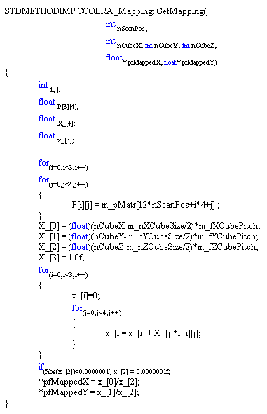
In 3D computing projective matrices are more popular (and typically convenient) though basically they carry the same information. So it is not any surprise that the matrices you get from our site are describing the complex scanner with (particularly) unstable U- and V-offset (case of complex gantry behavior). This is what matrices are for. Obviously one could use them to describe a good mechanics. But keep in mind that the corresponding reconstruction branch is 50% slower Unfortunately we have to say that Exxim does not have a technology/know-how for calibrating complex scanners. However we may utilize such information if somebody provides the matrices within the data. For example, a major Germen medical device manufacturer is using this approach pretty much in their C-Arm products - so COBRA can reconstruct their datasets. We also have an idea how this company does calibration but it is literally a high-level idea and certainly is not ready-to-use technology. In the same time it's possible that actually you do not need matrices - you just need more precise conventional calibration (though I am a little bit speculating here). And basic parameters would work well enough for you; they must be just more accurate (correct xxm file). Exxim has that technology and it might be a reasonable start unless you are 100% sure that the scanner is really such complex. Please also keep in mind that most likely if your gantry is "wobbly" then the approach of using matrices is "a way to nowhere". Some manufacturers use matrices mostly because (by many reasons) they use non-circular trajectories but all mechanics is still highly reproducible. Unfortunately I do not know any technology that can help if mechanics is not so good. Below there is the actual code of mapping (FYI)
22. How to install (uninstall) COBRA manually? Replacing Cobra version 6 by newer version1) Uninstall COBRA 6 by running 0_remove_cobra6.bat Run 0_remove_cobra6.bat by double click Replacing Cobra version 5 by COBRA version 6.x.x 1) Download and install Microsoft VC Redistributable runtime package 4) Unpack the content of zip into COBRA "residency" directory 4) Starting Cobra v 6.4.7 run the program checkPorts.exe and allow it to identify and fix possible firewall / TCPIP port conflicts For using GPU (see also below) the installation of Geforce 8800 drivers
The calibration in extended view is different from normal calibration, but they both can be done by COBRAGeoCalibration or COBRA_Geo. Please refer to the User Manual for more detail.
24. Give some more information about the data types and sizes of the preprocd_proj.000 file? The preprocd_proj.000 file is represented in the form as it is prepared for backprojecting. In general the size can be different. In simple words differences may be pretty big if such parameters are set: PARTAG_CROP_LEFT PARTAG_CROP_RIGHT PARTAG_CROP_UP PARTAG_CROP_DOWN PARTAG_TRANSPOSED_PRJ PARTAG_CATFORMAT PARTAG_HISFORMAT PARTAG_HBTC PARTAG_3XVIEW PARTAG_INPUTDOWNSAMPLE_X PARTAG_INPUTDOWNSAMPLE_Y The preprocd_proj.000 file is a simple file containing short signed integers (2 bytes per pixel). No header. The horizontal size is the same as in xxm file. Since COBRA is making automatic y-downsampling and loading only needed strip, a vertical size may vary.
25. How to define a factual slice number that have been saved on the disk in a stacked volume mode.
In SDK there is the following callback method that should be used In GUI you will see this number reported in a visualized log sequence (reconstruction progress tab)
26. Which type of PC (hyperthreaded, multi-core, etc.) should I use to get the best performance?
We have to distinguish three types of technology here:
27. How can I make a calibration phantom myself? A geometry calibration phantom is a plastic or alluminum cylinder. It must be made accurately and presizely. It means that any crossection perpendicular to the axis of symmetry must be accurately round. A phantom must be solid and stable. A phantom is hollow inside; phantom wall thickness is recommended to be about 1-2 mm. A phantom holds metal balls (beads). Basically a plastic or alluminum cylindrical body is important as far as it supports metal beads in accurate and known positions Diameter of bead is typically 1 mm or less. Beads must be put inside holes (hollows, depressions) and glued to a cylinder. Typically a cylinder holds 18-32 beads. Beads are forming 3 or 4 layers. Every bead layer contains 5-8 beads. In general a larger amount of beads increases a calibration accuracy. In the same time too many beads may create problems in distinguishing them on x-ray image Every bead layer is perfectly flat and the corresponding plane is perpendicular to the axis of cylinder symmetry. Distances between beads within the same layer and distances between layers are presize and uniform (stay the same) A diameter of phantom and it hight is defined by scanner field of view. It must be 25-40% smaller than FOV.
There are also a photo in our user manual, see Part 3, section 1.
|


